-
Help Support Hardline Crawlers :
You are using an out of date browser. It may not display this or other websites correctly.
You should upgrade or use an alternative browser.
You should upgrade or use an alternative browser.
Time to play with the big kids.
- Thread starter Pook
- Start date
Pook
Well-Known Member
Pook
Well-Known Member
Everything has been setup so I can switch to coilovers for going fast later. Just over 5" up travel in the front and 6" in the rear sitting at 18" belly height on 37"s.
longfield
Well-Known Member
Nice work Chris:awesomework:
Money Mark
Well-Known Member
- Joined
- May 19, 2006
- Messages
- 563
It's a-ight.....I guess.
stealthrunner1
Well-Known Member
How many gallon cell are ya running ???:eeek:
Pook
Well-Known Member
How many gallon cell are ya running ???:eeek:
Its an 8 gallon for now. Should do fine trail wheeling. If I want to go do KOH or BITD racing they have bigger cells with the same foot print just taller, so I can just slip this one out and drop a larger one in and just make new straps.:awesomework:
Pook
Well-Known Member
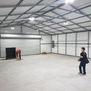
Well its still not painted but tweaking a few more things to get them were I want them. Had a fun weekend a little bit of fabbing, Wife had some plans this weekend with a friends so a bunch of hanging out with the kids and some good family RC crawling fun.
Colin came out and got the mounts made up for the 5 points, and got the exhaust fully finished up and ready for coating. :awesomework:
I got some hinge mounts made up for the hood and got the hood pins tacked in.
Colin came out and got the mounts made up for the 5 points, and got the exhaust fully finished up and ready for coating. :awesomework:
I got some hinge mounts made up for the hood and got the hood pins tacked in.
Attachments
Pook
Well-Known Member
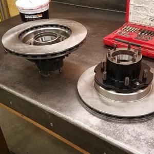
Went out and bought some new wheel bearings so we could mock up the steering angles and check out clearances.
Wasn't quite what I wanted at full turn on the outside wheel. It cleared on flat ground but the tire got real friendly when flexed up.
Wasn't quite what I wanted at full turn on the outside wheel. It cleared on flat ground but the tire got real friendly when flexed up.
Attachments
Pook
Well-Known Member
Pook
Well-Known Member
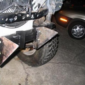
Decided on building a bolt on front bumper to bring the rig to max allowed clearances of Werock's specs. I could of cut farther back on the main tubes and re worked the shock towers but I decided to make a bolt on "frame extension" bumper thingy instead.
Goals were to get the bumper up to maximum height allowed which I understand it to be the top of the 37" tire and 16" between the frame rails at ride height.
A couple pluses to the bolt on bumper idea were it becomes somewhat disposable and easy to replace when it gets smashed up, and if I ever want more than 90deg approach angles I can just build a new bolt on bumper.
Start of the bumper and checking clearances when flexed.
(the flatbar mounting plate is just there for mock and will be getting cut up all fancy later :flipoff: )
Attachments
Last edited:
Pook
Well-Known Member
Front bumper getting a bit more shape to it. The plate will be getting cut up and Swiss cheesed for the winch once I jump a little hurdle with the winch.
I think it looks pretty good. Still need to add some braces back to the shock towers.
Just ignore the extra long temporary bolts:kissmyass:
I think it looks pretty good. Still need to add some braces back to the shock towers.
Just ignore the extra long temporary bolts:kissmyass:
Attachments
Clark
Well-Known Member
You are doing big things there Pook. Looks great:beer:
Binder
Well-Known Member
I love to see guys think out of the box when building things rather than just do it the way everyone else does. This rig is going to stand out first class!:awesomework:
Pook
Well-Known Member
Thanks, but I can't take credit for everything Jason and Trev have helped out with a lot of advice, and my friend Colin has also put in a lot of time and effort in getting things fabbed up.
Pook
Well-Known Member
I bought a smittybilt after reading some reviews on Pirate and seeing one first hand on my brother's samurai. The price was right at $299 from 4wheelparts with free shipping. http://www.smittybilt.com/product/index/38.htm
I sold the new steel cable that came on it and bought some winch rope from Rockstomper.
Since I got the new bumper mocked up I needed to figure out how to fit the winch. It was a little to wide. I had read a thread on Pirate a couple years ago on narrowing up a Ramsey winch so I figured it couldn't be to hard.
So I pulled the winch apart and checked out its guts.
Sorry about the pic quality, didn't realize the lens was dirty on my cell till the very end. Damn grinding dust.:looser:
If you look inside you can see the inside tube was machined slightly to fit what I assume is( or part of) the brake setup. The other end has a drive gear welded to it. So it wasn't going to be as simple as I thought.
Attachments
Last edited:
Pook
Well-Known Member
I thought about waiting till tomorrow and taking it to a friends machine shop to have them part it off on the lathe and possibly machine me a sleeve or rebore the tube...
but then I figured if I'm going to do that I might as well cut it up and see if I can find some tube to sleeve it with.
Started by carefully cutting the flange off the side with the gear welded on. I ground in till I could lightly tap it with a hammer and crack the weld. I then tapped it off.
but then I figured if I'm going to do that I might as well cut it up and see if I can find some tube to sleeve it with.
Started by carefully cutting the flange off the side with the gear welded on. I ground in till I could lightly tap it with a hammer and crack the weld. I then tapped it off.
Attachments
Pook
Well-Known Member
I went and looked up the measurements on a Warn RC9.0 so I could copy the bolt pattern in case I ever want to upgrade. The smittybilt had a 10" width on the bolt holes and Warn listed a 6" on the RC 9.0. So I marked it out allowed for the blade with and rigged up a way to clamp it in my bandsaw and started cutting.
I never realized how thick the drum was. After cutting the drum, I beveled the edges leaving just a slight flat spot.
I never realized how thick the drum was. After cutting the drum, I beveled the edges leaving just a slight flat spot.
Attachments
Pook
Well-Known Member
I then slipped a piece of bronze round stock I had left over from a project that fit somewhat tightly and dropped it in a V Block to square it all up. (a chunk of angle iron would work just as good.)
For fun (and practice) I tig welded the first pass on the drum, and then capped it with the MIG. I then ground it smooth using a sanding disk and then a scotch brite disk.
I left the slight burr were I had cut the round flange off to help me line it back up and tacked it on. Fully welded it up gave it a good cleaning.


![IMG_E8620[1].JPG](http://attachments.www.hardlinecrawlers.com/xfmg/thumbnail/12/12439-f526aa0adad629df5b811a8157997f30.jpg?1625929688)
