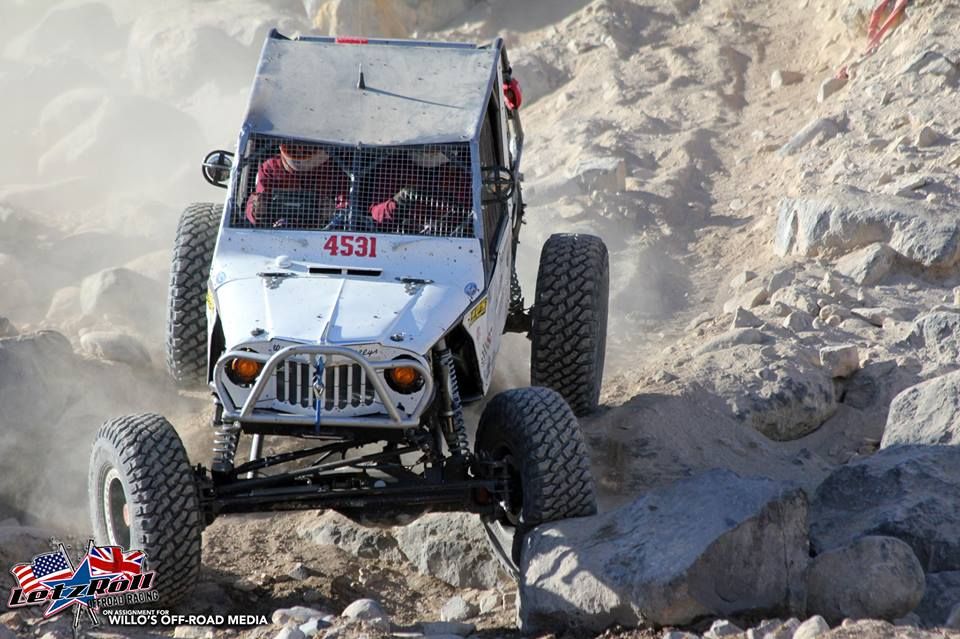
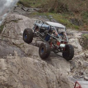
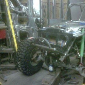
I've been meaning to post this for a while. There's not a lot of info out there on bell crank steering setups and when I built my buggy I had to figure it all out for myself. I wanted my buggy to be street legal and I wanted to maintain a mechanical link.
There are a few examples out there and you can get a few random pictures of parts and pieces but design criteria is hard to come by. Jessie Haines was nice enough to share his knowledge and experience But you're still pretty much on your own. One thing I'll say at the onset is it would be better to build your buggy around your steering than the other way around. I learned a ton and would do it differently if I was to do it again, but it seems to work fantastically. It hasn't seen any hard use yet but so far so good.
The steering box is mounted in the dash with a link down to a Bell crank under the floor pan. Well actually in the middle of the pan between the peddles. Then a link runs forward to another bell crank located in the front axle truss. The key to making it work without bump steer is to keep the steering link moving in the same arc as the suspension links. In the neutral steering position the steering link heims are inline with a line drawn between the two 4-link Heims on either end. There is undoubtedly some bump-steer but I can't prove it.
So that pretty much dictated where the bell cranks have to be located, the rest was just working out the particulars of bell crank arm lengths and such to make it all work out. The steering box, the wheel stops and the cylinder all have to bottom out at the same time.
I also tried to keep all opposing crank arm close to equal length and parallel. And perpendicular to the connecting rods. Knuckle steering arms same lengths as the associated bell crank arm, front and rear bell crank arms that are attached with the tie rod are equal length and parallel, bell crank arm and Pittman are same and parallel.
I also tried to keep arms and links at 90 degrees of each other in the neutral steering position To keep the arc lengths the same in either direction while turning.


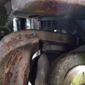
FRont Bell Crank


Rear bell crank


There are a few examples out there and you can get a few random pictures of parts and pieces but design criteria is hard to come by. Jessie Haines was nice enough to share his knowledge and experience But you're still pretty much on your own. One thing I'll say at the onset is it would be better to build your buggy around your steering than the other way around. I learned a ton and would do it differently if I was to do it again, but it seems to work fantastically. It hasn't seen any hard use yet but so far so good.
The steering box is mounted in the dash with a link down to a Bell crank under the floor pan. Well actually in the middle of the pan between the peddles. Then a link runs forward to another bell crank located in the front axle truss. The key to making it work without bump steer is to keep the steering link moving in the same arc as the suspension links. In the neutral steering position the steering link heims are inline with a line drawn between the two 4-link Heims on either end. There is undoubtedly some bump-steer but I can't prove it.
So that pretty much dictated where the bell cranks have to be located, the rest was just working out the particulars of bell crank arm lengths and such to make it all work out. The steering box, the wheel stops and the cylinder all have to bottom out at the same time.
I also tried to keep all opposing crank arm close to equal length and parallel. And perpendicular to the connecting rods. Knuckle steering arms same lengths as the associated bell crank arm, front and rear bell crank arms that are attached with the tie rod are equal length and parallel, bell crank arm and Pittman are same and parallel.
I also tried to keep arms and links at 90 degrees of each other in the neutral steering position To keep the arc lengths the same in either direction while turning.
FRont Bell Crank
Rear bell crank
Attachments
Last edited:


